Before I saw the video with the firmware, I thought about whether a chip could actually work if it was inserted the wrong way round.
And yes, it depends on the chip and the technology used, how it behaves. Let me describe some of my finds here.
In advance: There are people who, because of their narrow view of the world and poor understanding, just gossip and first blame without any evidence.
That shows stupidity. It is interesting to find out whether a chip can actually work that way.
I have just done a few experiments on this and the result is: It is possible under certain (several) conditions:
1. Requirement (structure of the chip):
=======================================
First of all, the gates must be arranged in a suitable manner so that when the chip is rotated, they are still connected.
This is not the case with the 7400, so the error should be detected with a suitable test pattern.
Let's simplify the circuit and take a chip in Diode logic with different gate positions.
see also
https://en.wikipedia.org/wiki/Diode_logic
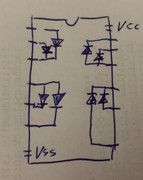
If you use this chip, you will see that it can be used the other way around, as the gates are mirrored.
2. Requirement (technology used):
=======================================
Let's think about what a power supply is used for.
With diode technology, you can do without power supply (with two parallel diodes you have an OR gate, completely without voltage supply).
However, each diode has a voltage drop of 0.7V, i.e. after a few diodes there isn't much left. In addition, as much power must be made available at the inputs as is required at the output for control. So the power supply is used to have a reference voltage that can be used.
Now we don't have diode logic, but TTL technology, i.e. transistors. Transistors are amplifiers that are used as switches in our purpose (we have to go into saturation for this).
Let's take the following transistor (two bases, so it is an OR gate, greatly simplified):

What happens in normal operation? Transistors (BJTs) are current controlled (not voltage controlled like (MOS)FETs).
With a low input current Ibe, a larger output current Ice is switched. In the circuits we use, the gain is not so important, but with e.g. 74xx chips, you still need an input current of 3-5mA(!) to switch cleanly. With the 74LSxx it is approx. 1-2mA.
I have already added a chapter in the manual that addresses this problem if a chip requires an increased input current of >5mA due to aging (the Chip Tester can only deliver a maximum of 5mA). Sometimes it will work, sometimes it won't.
Now, what happens if the Vcc and GND are omitted from the OR gate? That depends a lot on the chip. In the transistor example above, the OR gate will still work, but the input current does not switch Ice, but Ibe will be measurable at the output. If this is now normally loaded, the base will probably burn through, additonally a voltage drop of Ube can be measured. This transistor behaves like a diode.
What happens when you switch voltage polarity?
If there are no protective diodes (modern chips have them), the transistor is operated with the polarity reversed (i.e. C and E reversed). This works, but you do not have the full current gain and the transistor will probably not work long if it is loaded due to the different thicknesses of the layers.
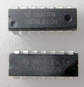
I did an experiment with the 74LS00. This has a special feature, an additional inverter (NAND-gate).
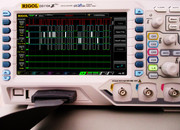
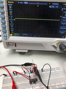
In normal operation it looks like this.
Power supply is available. Pin 1 and pin 2 are at Vcc in the picture, I measure a LOW at pin 3.
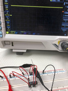
Now I remove GND:
There is still a LOW at the output, but now at around 0.7V (remeber the 0,7V voltage drop).
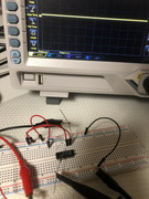
Now we set pin 2 to GND:
And, as expected, we get a HIGH. The chip also works without a correct power supply!
There are a few restrictions here, however. Due to the inverter, Vcc cannot be dispensed with and it can look different with other chips.
At least one input of another(!) gate must be connected to GND. (** more on this below). The internal structure of the chip would be interesting here to know.
If you want, you can try it out with other 74xx gates. I had limited the power supply to 10mA so that a chip would not be damaged.
And now comes the highlight:
-----------------------------
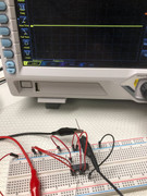
We reverse the supply voltage and see if it works:
You can see that I applied +5V to Vss and limited the current to 5mA with 1k Ohm, Vss is not connected to Vcc. Both inputs are HIGH, the output is HIGH.
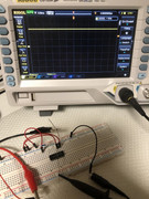
In the picture one input is at LOW, the output is too. In this configuration we have an OR gate.
So a NAND chip operated with the wrong polarity behaves like an OR gate in this experiment

At least one chip from this manufacturer. Chips from different munufacturers can have completely different structures.
The inverter is missing. If you like, you can do your own experiments and look and find out under which conditions a chip behaves and how.
3. Requirement (the test pattern):
=======================================
I programmed the firmware in such a way that the test patterns only make sense if the chip is correctly positioned in the socket.
If it sits rotated in the socket, it is operated with the wrong polarity, as shown above, anything can happen.
It is also very likely that Vcc or Vss will suddenly be applied to the outputs. In a real circuit the chip will be destroyed due to overheating (due to a possible shortcut, we learned not to connect an output to a Vcc or GND), but the Tester delivers only a maximum of 5mA, not enough to damage the chip.
Let's take another look at the transistor above: If a voltage is applied to the emitter, the emitter - base/collector junction blocks, but depending on how the circuit is constructed, this voltage could trigger a base on another transistor. What happens then depends entirely on the chip.
The Chip Tester uses e.g. Pullups at the outputs of the chips in order to be able to test Open Collector components. Even this small current <100nA could switch something if the chip was inserted the wrong way round.
The NAND gate from (2, **) would then be tested as error-free in the correct position if the test pattern is structured in such a way that at least one input of another gate is always HIGH or LOW (actually it is). But who is planning test patterns for an incorrectly inserted chip?
The result also applies to all testers: If a tester or device under test is operated outside of the specification, anything can occur.
The limits of the Chip Tester are described very clearly in chapter 8 of the manual. In the next issue there is another interesting example with a 7490 (non LS type) chip. If a chip is operated outside of the specification, anything can happen (e.g. a NAND gate becomes an OR gate).
If you are doing your own experiments, you will need an oscilloscope so that the outputs are not heavily loaded. An LED may not yet light up at <1mA, but the voltage level can still be clearly seen on the oscilloscope. The Chip Tester can also detect this well due to the high-resistance inputs. If you want, you can also write your own short program to check out these tests with the help of the Tester.
I use the Tester for about three years now, and yes, there are still TTL test patterns that have not been tested using a real chip (I have not all chips available and lots of patterns I did manually using the datasheets). That can always happen and when you find such a bug I will fix it (see the changelog).
Again: No Tester can detect 100% of the possible faults. With the March-Y and March-U tests you will detect >90% of the possible faults (no signal level related faults etc., see chapter 8 again) and 99.9% of the defect chips in the wild.
The TTL tests are not so sophisticated, you will recognize also >99% of all defects when you use the Tester/Chip in its specification. When you try to test a chip that needs an input current >4-5mA you cannot expect that the chip will be tested ok even when it works fine (that is very rare, only a very few 74xx chips need so much current at their inputs).
And of course: When you do modifications at the firmware or when you modifies the hardware (e.g. using other transistors or diodes) you might also get wrong results.