Página 3 de 23

Re: Manual de montaje del superupgrade

Publicado: 16 Ago 2014, 01:04
por wilco2009
Thanks a lot, velesoft.

Your suggestions will be a great help.

Re: Manual de montaje del superupgrade

Publicado: 16 Ago 2014, 01:11
por wilco2009
velesoft escribió:
wilco2009 escribió:Y la segunda es el esquema del circuito, para verlo en grande pinchar sobre la imagen.

Imagen
In GAL A equations I see some bugs.

1) small compatibility with ZX128 memory - none memory pages mirroring

2) it's not ZX16 to ZX512kB expansion, but it's add 512kB = 16kB+512kB

3) impossibility disable 512kB may cause incompatibility with other software for ZX128 (some 128k software crash is you use paging bits D6 and D7)

Here is fixed equations for your GAL A: (100% memory compatibility with Pentagon 512kB)
[anchor= goto=]SA14 = A14*A15*BANK0
+ A14*/A15

SA15 = A14*A15*BANK1
+ /A14*A15

SA16 = A14*A15*BANK2
+ A14*/A15

/SA17 = A14*A15*BANK3

SA18 = A14*A15*BANK4[/anchor]

If you set address lines SA17 and SA18 to log.0, then my equations will 100% compatible with memory paging on ZX128. Will work also software which use memory mirroring (ram page 5 is mirrored on address 16384, ram page 2 is mirrored on address 32768). If any games use mirroring to page 5 (=set 7FFD to value 5 and write from address 49152) then upgrade will detect it and write data to correct ram, you can't see correct videoram data, but CPU will always read 100% correct data. Software always detect this memory upgrade as 100% compatible, only visual data in first videoram (on TV out) can be some times different.
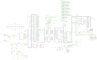
It is possible to disable SA17 and SA18. we have two jumpers to do it.

About the equations, I have to read them in detail. It is very interesting that you say about mirroring page 5. I thought it is not possible without internal modifications in the Speccy.

Re: Manual de montaje del superupgrade

Publicado: 16 Ago 2014, 01:43
por velesoft
wilco2009 escribió:About the equations, I have to read them in detail. It is very interesting that you say about mirroring page 5. I thought it is not possible without internal modifications in the Speccy.
Yes, it's possible because memory databus(videoram) in range 16384-32767 is connect with CPU via resistors 470 Ohm.

For example:
- if CPU read byte from address 16384 then read videoram data
- if you in same time connect external memory then videoram data have low priority(thanks to resistors) and CPU read data from your exteranal memory

This feature enable full 100% memory compatibility with 128kB, but only for CPU. Software will see original ZX128 memory layout and memory mirroring. Incompatibility will only visual - thanks to absence second videoram and only emulation of mirroring of page 5.

Command SNAPLOAD in esxdos system contain my new routines for better loading 128kB snapshots. :-)

Re: Manual de montaje del superupgrade

Publicado: 16 Ago 2014, 09:41
por wilco2009
Many thanks, velesoft.
I will change the equations inmediately.

Re: Manual de montaje del superupgrade

Publicado: 17 Ago 2014, 00:07
por wilco2009
I implemented your suggested changes in the GAL equations and everything seems work fine.
Now I need a game that use mirroring in page 5 to test it.

By other hand, I made some changes in the add-on.

I have added more functionality to the port $043B.

D0..D4: 16Kb ROM block (D0,D1-ROM Page, D2..D4- 64Kb ROM block)

D5: Disable $7FFD ROM Paging (DIS_ROMA14)
D6: Disable $1FFD ROM Paging (DIS_ROMA15)

D7: Disable divIDE (DIS_DIVIDE)

The way it will work will be as following:

-1 When reset DIS_A14, DIS_A15 and DIS_DIVIDE will set to 1.
-2 BIOS ROM will work without problem because divIDE is not active.
-3 In BIOS ROM we have a list of ROMs, and for each ROM we will have:
----3a) Description
----3b) Position in flash ROM (0..31)
----3c) ¿divIDE disabled?
----3d) ROM size in 16Kb blocks
------------If Size = 1 then DIS_A14 = 1 and DIS_A15=1
------------If Size = 2 then DIS_A14 = 0 and DIS_A15=1
------------If Size = 3 then DIS_A14 = 1 and DIS_A15=0

When we will select a ROM, the BIOS program will activate, divIDE and ROM pagging as is configured for the selected ROM, and then will change page ROM and jump to 0.

Pressing Reset disables ROM pagging and divIDE and activates BIOS (16Kb block 0).

Some Hardware modifications on the add-on are needed:

Imagen

And the equations for the add-on GAL:

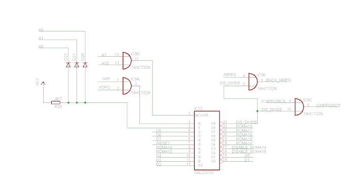
Código: Seleccionar todo

DISABLE_ROMA14     = !(  COND & !COND2 & !D5 & RESET & !COND3 
                      #   !COND & RESET & !DISABLE_ROMA14 
                      #   COND2 & RESET & !DISABLE_ROMA14 
                      #   RESET & COND3 & !DISABLE_ROMA14 );

DISABLE_ROMA15     = !(  COND & !COND2 & RESET & !COND3 & !D6 
                      #   !COND & RESET & !DISABLE_ROMA15 
                      #   COND2 & RESET & !DISABLE_ROMA15 
                      #   RESET & COND3 & !DISABLE_ROMA15 );

DIS_DIVIDE     = !(  COND & !COND2 & RESET & !COND3 & !D7 
                  #   !COND & RESET & !DIS_DIVIDE 
                  #   COND2 & RESET & !DIS_DIVIDE 
                  #   RESET & COND3 & !DIS_DIVIDE );

ROMA14_2     = (  COND & !COND2 & RESET & D0 & !COND3 
                #   ROMA14_2 & DISABLE_ROMA14 
                #   ROMA14 & !DISABLE_ROMA14 );

ROMA15_2     = (  COND & !COND2 & RESET & D1 & !COND3 
                #   ROMA15_2 & DISABLE_ROMA15 
                #   ROMA15 & !DISABLE_ROMA15 );

ROMA16     = (  COND & !COND2 & RESET & !COND3 & D2 
              #   !COND & RESET & ROMA16 
              #   COND2 & RESET & ROMA16 
              #   RESET & COND3 & ROMA16 );

ROMA17     = (  COND & !COND2 & RESET & !COND3 & D3 
              #   !COND & RESET & ROMA17 
              #   COND2 & RESET & ROMA17 
              #   RESET & COND3 & ROMA17 );

ROMA18     = (  COND & !COND2 & RESET & !COND3 & D4 
              #   !COND & RESET & ROMA18 
              #   COND2 & RESET & ROMA18 
              #   RESET & COND3 & ROMA18 );
Where
COND = pin 3
COND2 = pin 1
COND3 = pin 2

@VELESOFT: Some suggestions about it before start with the hardware?

Re: Manual de montaje del superupgrade

Publicado: 17 Ago 2014, 14:09
por flopping
Muy buenas sugerencias y parece que van muy bien, ¿necesito el hardware extra o sólo con cambiar el programa de las gals es suficiente?, aún así, le haré el añadido a algún interface, pero de momento con los jumpers nos podremos apañar, ¿es correcta mi suposición?, es decir, las ideas de velesoft, se pueden aplicar al circuito sin añadir nada más, sólo cambiando las ecuaciones de las gals, ya que el añadido es para poder usar las roms sin los jumpers, pero con ellos podemos apañarnos más o menos igual, ¿no?, bueno ya nos irás diciendo como van esos cambios y ya nos pasarás los jedec de las gals, jejejeejeje....salu2.

Re: Manual de montaje del superupgrade

Publicado: 17 Ago 2014, 17:17
por wilco2009
Efectivamente flopping, si se usan los jumpers no hace falta todo esto que estoy comentando.
Las ecuaciones propuestas por velesoft si que son convenientes, por lo que ya publicare los archivos jed.

Publicare tambien un romset con solo ocho roms para utlizar con jumpers, ya que la que estoy enviando con los kits lleva 31 roms para usar con el menu.

Re: Manual de montaje del superupgrade

Publicado: 20 Ago 2014, 21:40
por JULIO
Ya tengo el kit en mis manos, he repasado de p a pa todo lo que hay que hacer y veo una cosilla importante.
Para evitar que el divIDE (o lo que sea que conectemos detrás) se quede muy elevado
hay que soldar la expansion posterior a la MISMA ALTURA que el conector del bus, no es nada complicado y
soldando el conector sobre la tira de postes aumenta la distancia del interface con el spectrum, (porque luego habrá
que hacerle una caja)


Para poner la plaquita adicional yo voy a poner zocalo torneado en IC6.

En cuanto tenga fotos las paso por aquí.

Re: Manual de montaje del superupgrade

Publicado: 20 Ago 2014, 22:10
por flopping
Ojo con el bus trasero, si lo conectas directamente al conector de expansion, el divide no te funcionara y puede que mas cosas tampoco, ya que la conexion no va pin a pin.

Re: Manual de montaje del superupgrade

Publicado: 20 Ago 2014, 22:44
por wilco2009
Exactamente, hay que soldar el conector de expansión en el lugar destinado a tal efecto. Hay pines que no corresponden por lo que es OBLIGATORIO hacerlo ahi.